CAC Wirraway Technical Details
Technical details and background information about the Commonwealth Aircraft Corporation Wirraway aircraft, an Australian-built training and general-purpose aircraft which served in the RAAF from 1939 to 1959.
Systems

During the research for my drawings of the CAC Wirraway aircraft, I've collected a range of detailed technical information about this aircraft. On this page I have collected some of this technical information for viewing, as well as providing some links to additional websites or sources.
This page does not provide details about the history of the service use of the aircraft or the units which flew the Wirraway, since that is already covered well by other websites (see the list of links lower down the page).
If you have any comments or corrections or additions, feel free to send an e-mail to derek "at" buckmasterfamily "dot" id "dot" au
Also note that this information is only provided for historical interest, it should not be used in any way for the servicing or repair of aircraft.
All photographs are © Derek Buckmaster unless noted otherwise.
Development
The Wirraway is an Australian-built version of the North American Aviation NA-16-2K advanced trainer, the design of which was licensed from NAA for production in Australia. The Wirraway is a "cousin" to the well-known T-6 Texan trainer and the Harvard trainer, as all three aircraft were developed from the same "ancestor" - the NA-16 basic trainer which first flew in 1935.
Click here to read about the development of the Wirraway on the CA-1 page.
Variants
The Wirraway was built in 3 distinct versions (Mk I, Mk II and Mk III) and orders were placed in 7 different batches (contract numbers CA-1, 3, 5, 7, 8, 9 and 16). A total of 755 Wirraways were produced by Commonwealth Aircraft Corporation at Fisheman's Bend in Melbourne, with deliveries between July 1939 and June 1946. The correspondence between versions and CAC contract numbers is listed in the table below:
| Version: | CAC Contract Number: | Number produced under this contract: | RAAF serial numbers: | Comments: |
| Mk I | CA-1 | 40 | A20-3 to A20-42 | The first order for 40 aircraft was placed under Contract Demand T.374 on 15/3/1938 and also included 10 spare Wasp engines. |
| Mk II | CA-3 | 60 | A20-43 to A20-102 | |
| Mk II | CA-5 | 32 | A20-103 to A20-134 | |
| Mk II | CA-7 | 100 | A20-135 to A20-234 | |
| Mk II | CA-8 | 200 | A20-235 to A20-434 | |
| Mk II | CA-9 | 188 | A20-435 to A20-622 | CA-9 was originally expected to be the final contract for Wirraways, however another order was placed after this contract was completed. The final CA-9 aircraft (the 620th aircraft) was delivered in June 1942. |
| N/A | CA-10 | CA-10 was a project for a dive-bombing version of the Wirraway, which was never built | ||
| N/A | CA-10A | CA-10A was a contract for the construction of outer wing sets incorporating upward-moving split flaps (acting as dive-brakes for dive-bombing) which were retro-fitted to earlier aircraft. | ||
| Mk III | CA-16 | 135 | A20-623 to A20-755 | R.A.A.F. Contract Specification No. 10/42 was approved by the Directorate of Technical Services on 16 July 1943 for the production of Wirraway Mk III aircraft by Commonwealth Aircraft Corporation. Click here to view a copy of the specification. |
| Mk III | CA-20 | CA-20 was a contract for modification of Mk III Wirraways for delivery to the RAN. A total of 17 aircraft were modified. |
During the operational life of the Wirraway 79 Technical Instructions and 184 Technical Orders were issued relating to changes in the structure, equipment and operation of the aircraft. So apart from the major variants listed above many detailed changes were introduced to individual aircraft as they went through scheduled servicing.
Dimensions
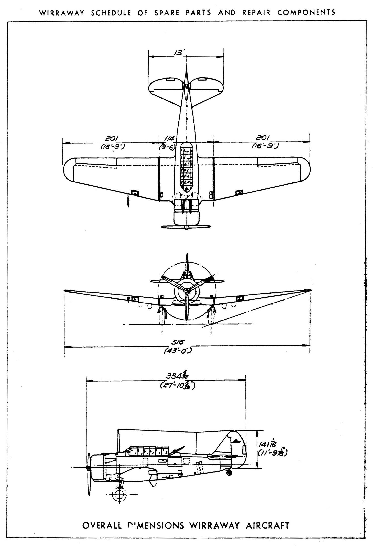
The drawing below shows the general dimensions for the CAC Wirraway.
|
This drawing is scanned from the Wirraway spare parts
manual issued in 1941. It shows a very basic general
arrangement drawing of the Wirraway Mk I with major
dimensions shown. Click on the thumbnail at the left to
view a larger image. Note that the wingspan is dimensioned as 43 ft 0 in (13.11 m), however this is incorrect as it represents the span of the wing as if the panels were all laid flat and does not take into account the dihedral on the outer wing panels (which reduces the span slightly). The correct wingspan is 42 ft 10˝ in (13.07 m). |
|
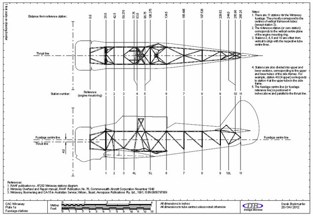
Fuselage station diagram, showing the reference stations which define the geometry of the fuselage. Click on the thumbnail to open a PDF file formatted to print on A4 paper. |

|
Wing station diagram, showing the reference stations which define the geometry of the wings. Click on the thumbnail to open a PDF file formatted to print on A4 paper. |
Construction
The Wirraway represented typical construction for an aircraft designed in the US in the mid-1930's. It featured some new construction techniques for the time (such as stressed-skin construction for the wings) along with traditional methods (such as the welded steel tube and fabric covering on the fuselage). Since it was designed as a training aircraft it also included a number of features intended to facilitate repairs and servicing (such as easily replaceable wing-tips and outer wings, removable access panels along both sides of the fuselage and modular horizontal stabilizer construction).
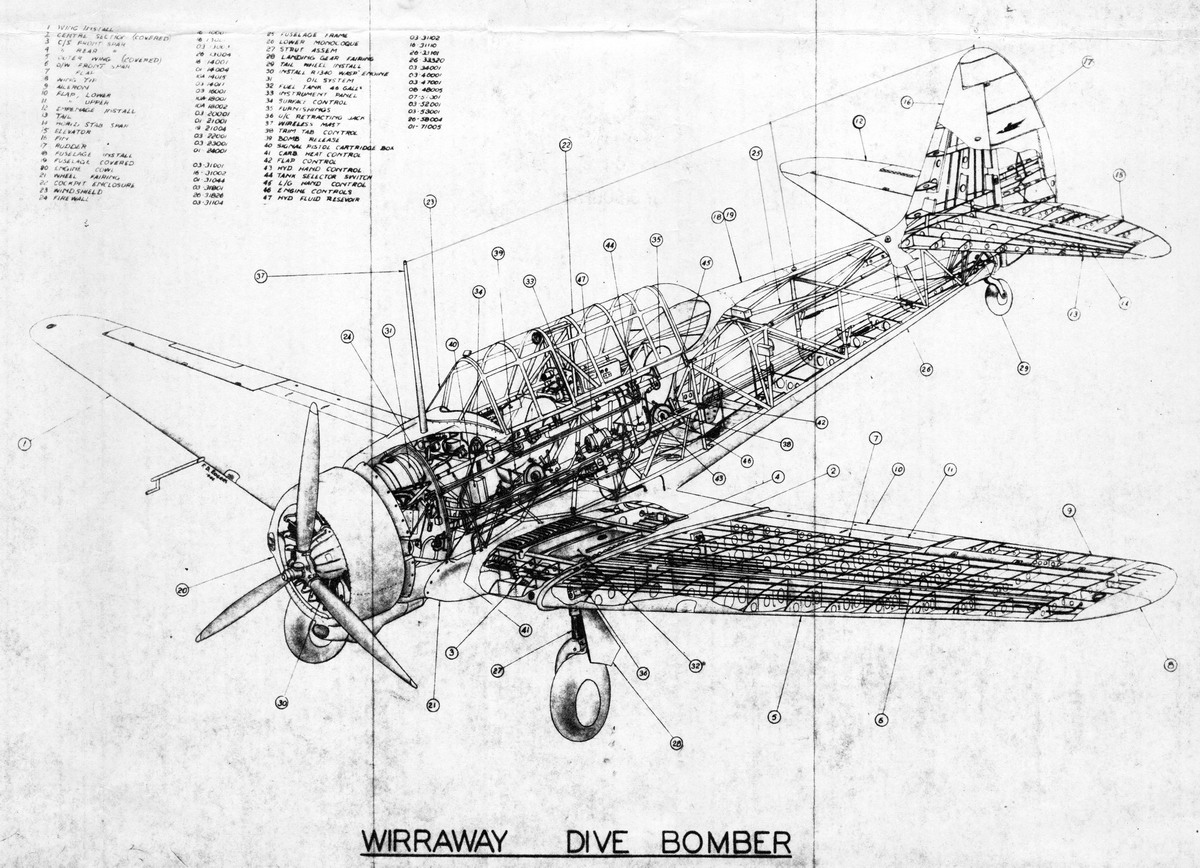 |
This cutaway drawing of the Wirraway was drawn by F.D. Rogers in 1944. It shows the internal structure and the layout of the major equipment. The drawing appears to show a CA-9 aircraft which has been retro-fitted with "dive bomber" wings (with airbrakes above the flaps) and no fixed forward armament. The quality is not very good, due to the blueprint reproduction process, but this interesting drawing shows the technology of aircraft design in the mid-1930's when the Wirraway was designed. Click on the thumbnail at the left to view a larger image. |
Engine
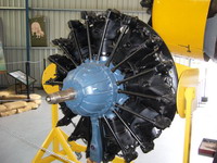
CAC-built Pratt & Whitney Wasp R-1340 S1H1-G engine:
The Wasp was the first engine produced by Pratt & Whitney Aircraft Co. following the establishment of the company in 1925. Fred Rentschler and George Mead left the Wright Aeronautical Corporation to form the company with Clayton Burt (President of Pratt & Whitney Company, a machine-tool company originally established in 1860).
The first Wasp engine to be developed was fired into life on Christmas eve of 1925. It was a 9-cylinder air-cooled radial engine with a displacement of 1,340 inł (hence the designation of R-1340) and it developed 425hp by it's third test run. Many developments and versions of this basic engine followed, and the S1H1-G model which powers the Wirraway produces 600hp and features a 12:1 supercharger (the supercharger impeller spins at 12 times the crankshaft speed) and a 3:2 geared propeller drive shaft (the propeller spins slower than the engine - at 66.7% of the crankshaft speed).
|
Detailed photos of the CAC-built Pratt & Whitney R-1340 S1H1-G engine on display at the Australian National Aviation Museum in Moorabbin, Australia. Click the thumbnail at the left to view the photos on Flikr. |
|
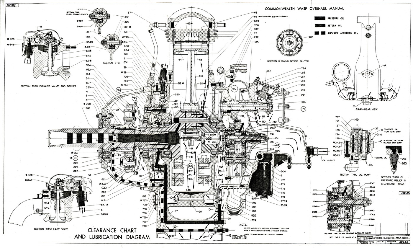
Clearance index chart from the engine overhaul manual (sheet 1 of 2). This drawing shows an interesting cross-section view of the engine. The numbers on the drawing correspond to clearances for the listed dimensions, which are described on a separate chart (not shown). Click on the thumbnail at the left to see the full-sized image. |
|
Clearance index chart from the engine overhaul manual
(sheet 2 of 2).
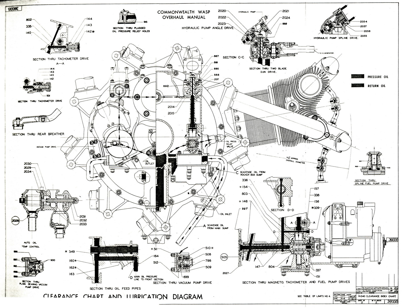
This drawing shows a view of the rear of the engine where the accessories (starter motor, magnetos, carburettor, oil pump, oil filter, etc) are mounted. Click on the thumbnail at the left to see the full-sized image. |
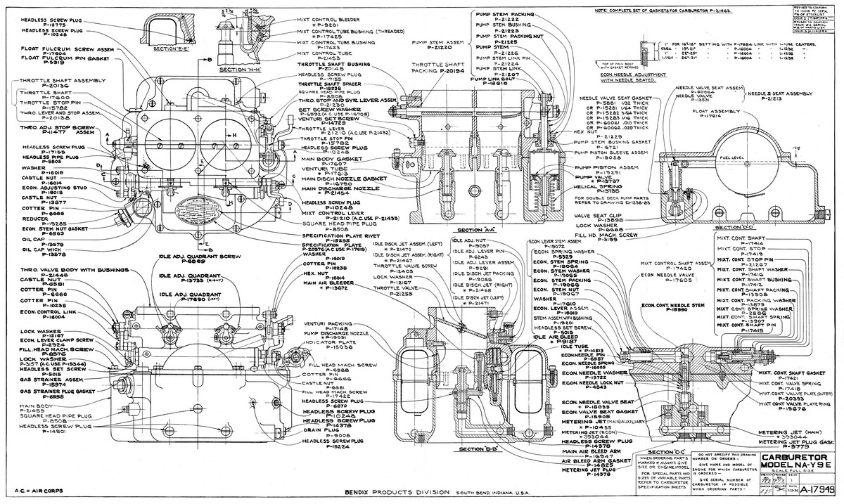
Stromberg NA-Y9H carburettor:
|
Schematic diagram showing all parts labelled. Click on the thumbnail at the left to see the full-sized image. |
Bendix-Scintilla SB9R magnetos:
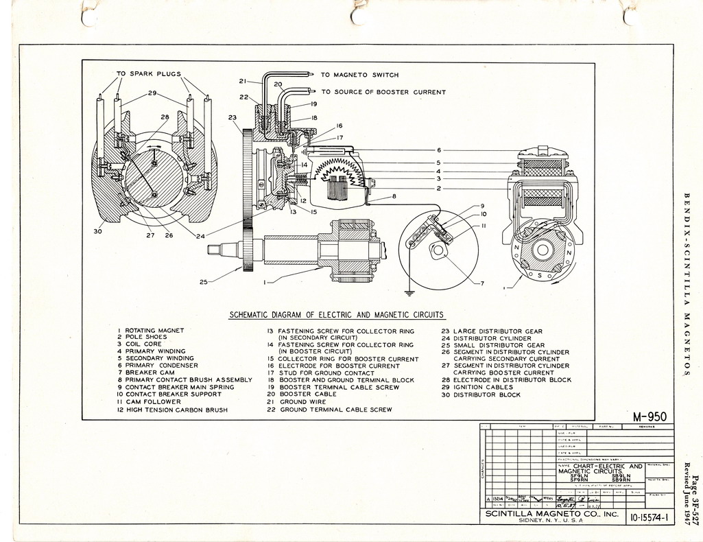 |
Schematic diagram showing electric and magnetic circuits. Click on the thumbnail at the left to see the full-sized image. |
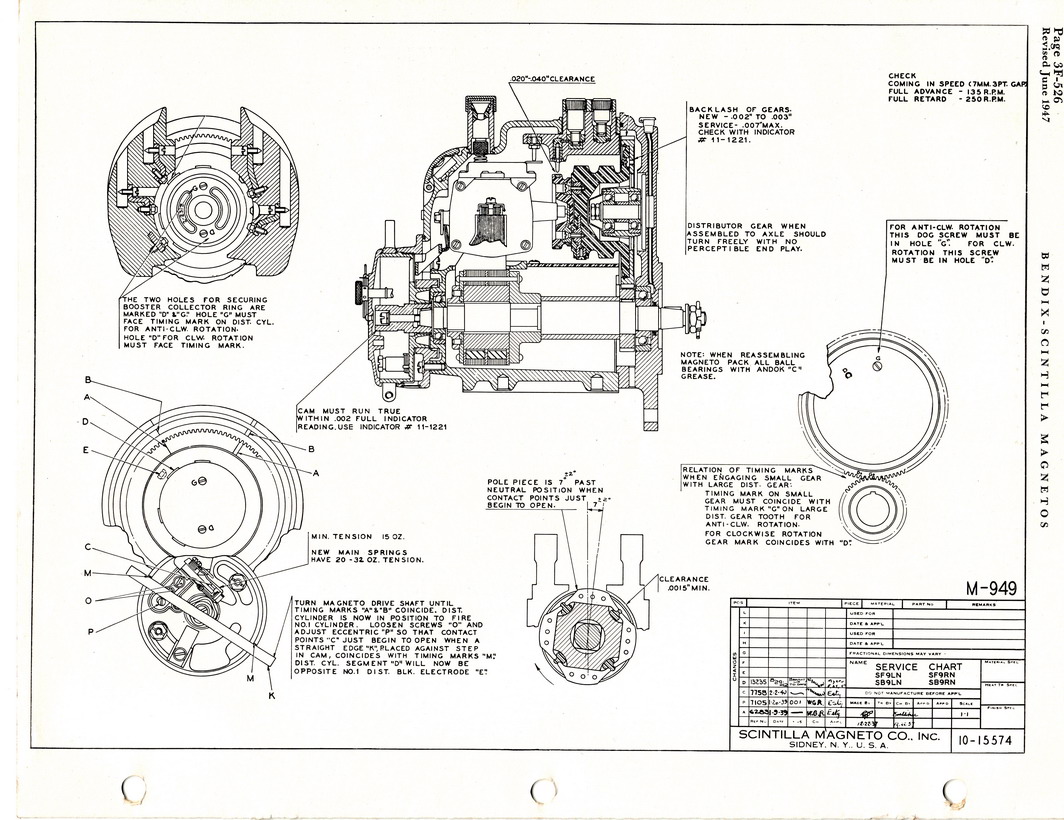 |
Service chart showing maintenance and installation instructions. Click on the thumbnail at the left to see the full-sized image. |
Propeller
The Wirraway was fitted with a 10 foot diameter De Havilland ADH2 constant speed propeller. The design for this propeller was licensed from Hamilton Standard, and the version fitted to the Wirraway corresponds to the Hamilton Standard 3D40 constant speed hub with 6101A-3 forged aluminium blades. The part numbers for these items provide the following descriptions:
3D40 hub description:
3 = 3 blades
D = Blade shank size "D"
40 = SAE #40 prop shaft spline size
Pitch range of this hub = 20°
High pitch setting = 39°
Low pitch setting = 19°
6101A-3 blade description:
6101 = basic blade design
A = the blade is an Assembly (including the blade itself, bearing
assembly, chafing ring, bushing, bushing drive-pins, bushing
drive-pin screws, and balancing-plug assembly)
-3 = the length of each blade is reduced from the basic design to
achieve a 3 inch reduction in the overall diameter
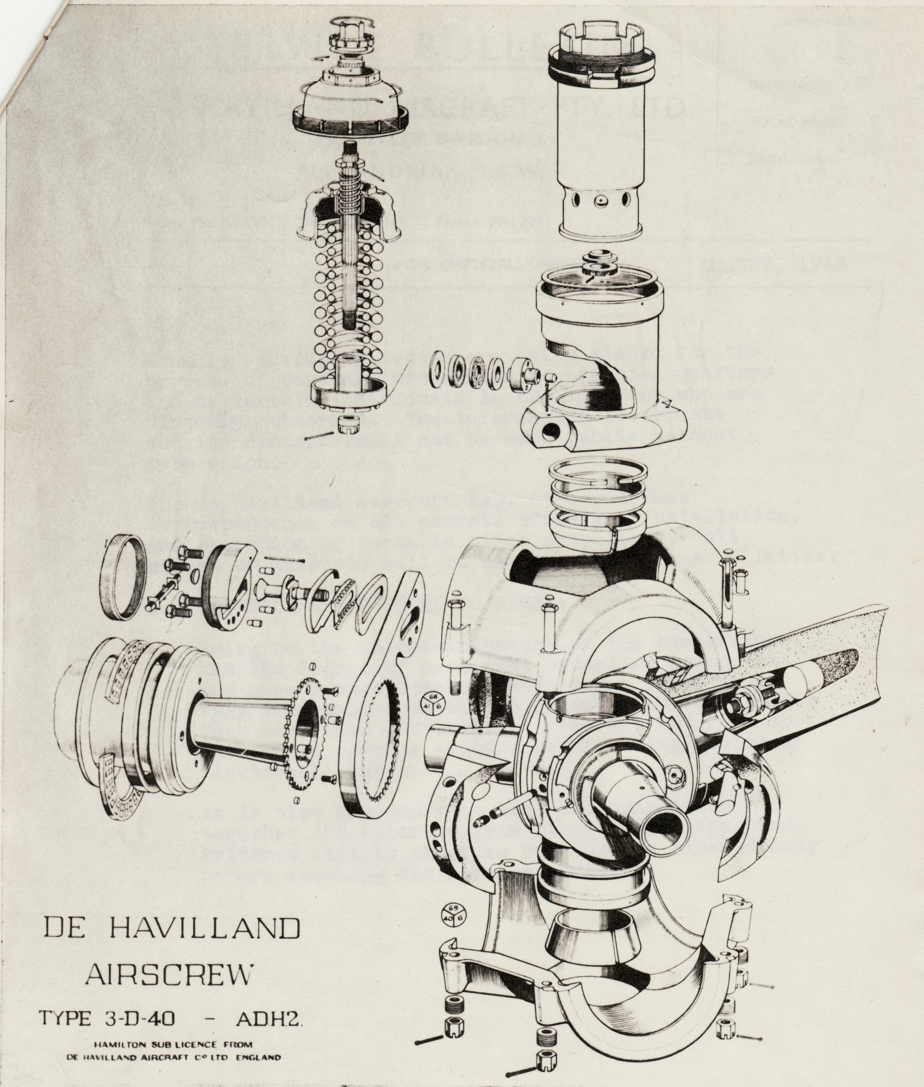 |
Exploded view of the De Havilland ADH2 propeller hub, which was a license-built Hamilton Standard 3D40 hub. This image was scanned from a 1942 monthly technical bulletin issued by De Havilland in Australia. Click on the thumbnail at the left to see the full-sized image. |
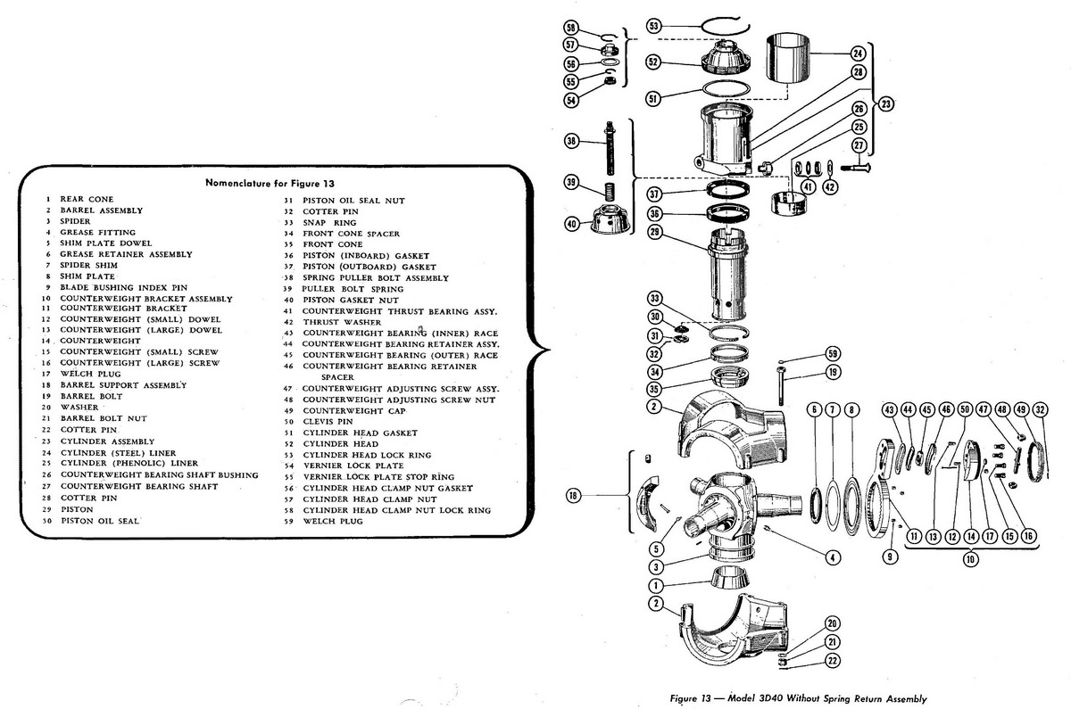 |
Exploded view of the Hamilton Standard 3D40 constant speed hub showing all parts labelled. This drawing is reproduced from the Hamilton Standard maintenance manual. Click on the thumbnail at the left to see the full-sized image. |
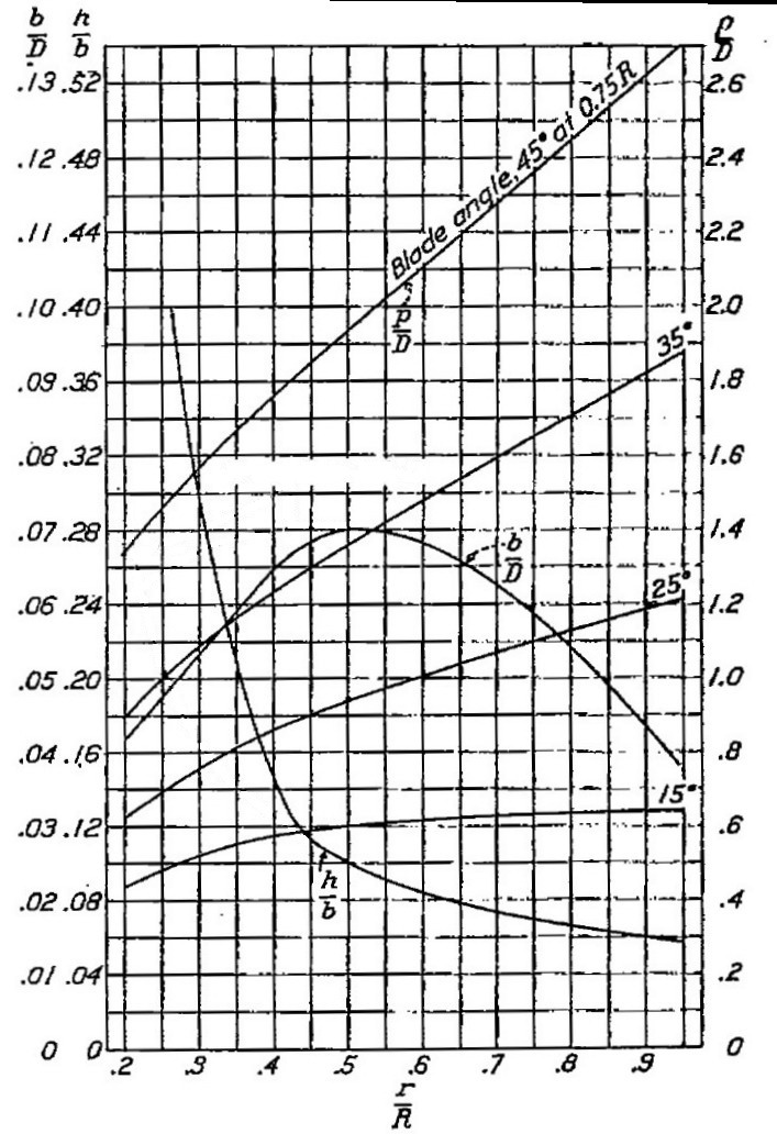 |
Blade form curves for the basic Hamilton Standard 6101
blade design. These curves show the following ratios at
different locations along the radius of the blade: p/D = pitch / Diameter (shown at 4 different pitch settings) b/D = chord / Diameter h/B = airfoil thickness / airfoil chord (the 6101 blade design uses the Clark Y airfoil section) Click on the thumbnail at the left to see the full-sized image. |
Armament
Guns:
The Wirraway can be equipped with two forward-firing fixed machine guns triggered by the pilot and one flexible aft-firing machine gun triggered by the observer.
Mounting points built into the steel-tube framework allow for two 0.303 in (7.7 mm) Vickers Mark V machine guns to be mounted in front of the windscreen, synchronised to fire through the propeller arc. Each gun is supplied with 600 rounds of ammunition in a removable magazine fitted below the guns which is accessed via a hinged panel on the starboard side of the forward fuselage. Spent shell casings and links are fed by a chute to a container between the wheel-wells in the wing centre-section, just aft of the oil-cooler air outlet.
The forward-firing guns were aimed with a ring-and-bead sight which was offset to the starboard side of the aircraft centre-line. The ring was mounted on the coaming above the instrument panel inside the wind-shield, and the bead was mounted on the front cowling between the troughs for the machine-gun barrels.
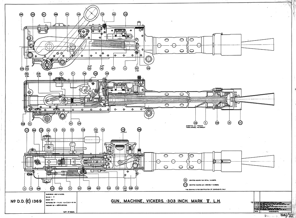 |
General arrangement drawing D.D.(E) 1369 showing details of the left-hand feed version of the Vickers Mark V 0.303 in calibre aircraft machine gun. Click on the thumbnail at the left to open a full view of the drawing. |
When fitted, a track in the rear cockpit can be equipped with a hydraulically-powered hoist for mounting a 0.303 in (7.7 mm) Vickers GO (gas operated) No. 1 Mark 1 machine gun to be fired by the observer. The Vickers GO was fed by a circular drum magazine clipped to the top of the gun, holding 60 rounds in each magazine. Wirraways normally carried 8 ammunition magazines, allowing 480 rounds for the oberver.
 |
General arrangement drawing of the Vickers Gas Operated (G.O.) Mark 1 Number 1 0.303 in calibre aircraft machine gun. Click on the thumbnail to open the full drawing. |
|
|
Picture showing the Vickers G.O. machine gun mounted in
the rear cockpit of an unknown Wirraway. The chute and
bag for collecting shell casings is clearly visible, as
are the fins on the gunsight bead (close to the muzzle).
These fins were intended to compensate the aim for the
effect of airspeed, but they were often removed (as
evident from later photographs) so they may not have
been very effective, or caused more maintenance issues
than they were worth. Click on the thumbnail to view a larger version of the photo on the AWM website. |
Some squadrons implemented a field modification to mount 2 Vickers G.O. machine guns on the track in the rear cockpit. In this case the ring and bead sights were mounted between the guns on brackets attached to their original mounting points.
|
|
Here is a Wirraway of 4 Squadron RAAF showing how two
Vickers G.O. machine guns could be mounted on the ring
in the rear cockpit. Click on the thumbnail to view a larger version of the photo on the AWM website. |
Later in their service life a number of Wirraway aircraft were modified to carry two 0.303 in (7.7 mm) Browning Mk II machine guns under the wings, with ammunition carried inside the wings. The wiring used for the release solenoids for the two outer bomb slips was modified to allow selection of guns or bombs. The details of the wiring changes were issued in a series of Technical Orders:
- Wirraway Technical Order 127 (December 6, 1944) "Wing guns electrical installation", to be carried out in accordance with Armament Order 4B/9;
- Additional Wirraway Order 140 "Installation of fixed firing buttons for gun bomb" was issued;
- This was superseded by Wirraway Order 146 (March 3, 1950) "Firing buttons for gun bomb and CCG - installation on front control column";
- Finally, Wirraway Order 150 (June 30, 1950) "Wirraway wing guns - electrical installation" was issued as well.
The guns were mounted sideways under the wings on brackets held in place by 4 of the existing bomb steadies. The front of the gun was supported by a ring around the blast tube adapter (at the rear of the barrel) which was supported by a u-shaped bracket. This enabled the gun to pivot sideways and vertically for setting the convergence point. The rear of the guns was mounted with a single bolt through the mounting bracket which could be traversed inboard and outboard or adjusted vertically with the bolt threads.
The wing-mounted guns were sighted with a Mark II reflector gun-sight, fitted according to Wirraway Order 134 - Reflector Sight Mk II Installation.
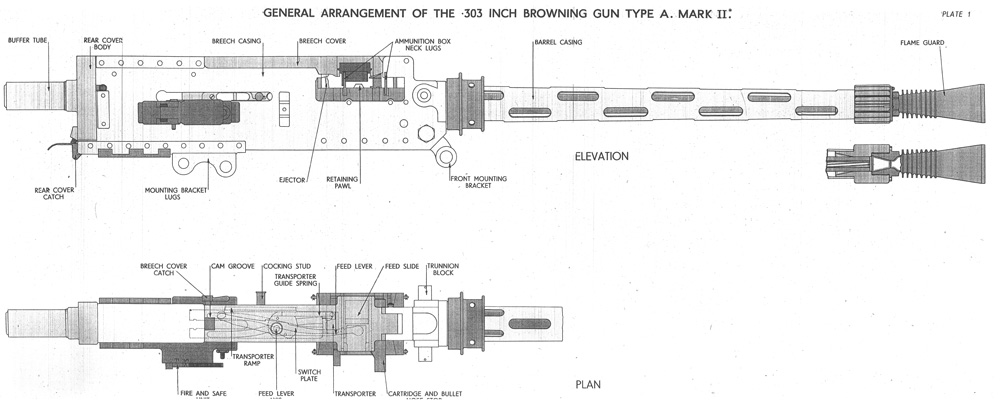 |
General arrangement drawing of the Browning Mark II 0.303" aircraft machine gun. Click on the thumbnail to open the full drawing. |
Bombs:
The Wirraway has a total of 18 "slips" below the wings from which bombs, pyrotechnics (flares) or supply containers can be dropped.
4 universal carriers on the outer wings (2 per side, slips 1, 2, 3 and 4) for carrying up to 500 lbs of bombs. These universal carriers are activated electrically from the bombing controls in the front or rear cockpit. They could be used for the following:- 100 lb anti-submarine (A.S.)
- 112 lb high explosive (H.E.)
- 120 lb general purpose (G.P.)
- 250 lb general purpose (G.P.)
- 250 lb semi armour-piercing (S.A.P.)
- 250 lb anti-submarine (A.S.)
- 250 lb high explosive Royal Laboratory (R.L.)
- Storepedo 16" Mark I (200 lb capacity)
On aircraft numbered A20-30 and higher the two inboard universal carriers (slips 1 and 2) are strengthened to carry 500 lb S.A.P. bombs, in which case the maximum bomb load is 1,000 lbs.
6 light series carriers on the centre section (3 per side, slips 5, 6, 7, 8, 9 and 10). These light series carriers are activated electrically from the bombing controls in the front or rear cockpit. The could be used for carrying:
- 8˝ lb Mark 1 practice bombs or
- 11˝ lb Mark 1 practice bombs
8 mechanically-controlled carriers on the centre section for carrying:
- 4-inch reconnaissance flares
Pyrotechnics:
Two tubes are mounted in the aft fuselage for launching 4-inch reconnaissance flares. The doors on the lower ends of the tubes are opened by control cables in the front cockpit. A Verey signal-flare pistol with 8 cartridges is carried in front cockpit.
Manuals
 |
The Wirraway Overhaul and Repair Manual RAAF Publication No. 76 Issued by the Engineering Department, Aircraft Division of Commonwealth Aircraft Corporation Pty Ltd, November 1940 This manual covers all the information required for servicing and repairing the Wirraway aircraft. The manual is divided into 3 parts:
You can order an electronic copy in PDF format from Mach One Manuals. |
 |
Pilot's Notes for the Wirraway Aircraft RAAF Publication No. 109 This manual covers all the information required for operating the Wirraway aircraft. This includes notes for pilots and descriptions of operating all the aircraft equipment and controls. You can sometimes find copies available on eBay, or order an electronic copy in PDF format from Mach One Manuals. |
 |
CAC Wasp Operating Instructions RAAF Publication No. 71 |
 |
Overhaul Manual for the Commonwealth Wasp Type S1H1-G Aircraft Engine RAAF Publication No. 156 August, 1941 (Revised June 1946) |
Bibliography
A selection of books, magazine articles and newspaper articles related to the Wirraway:
- Caruana, Richard J. The Commonwealth Aircraft Company Wirraway. Scale Aviation Modeller International magazine. Volume 9 Issue 11, November 2003
- Davis, Larry. T-6 Texan In Action. Aircraft Number 94, Squadron/Signal Publications, 1115 Crowley Drive Carrollton Texas, 1989 (includes a chapter on the Wirraway)
- Gillison, Douglas (1962), Royal Australian Air Force 1939-1942.Australia in the War of 1939–1945. Series 3, Volume 26 – Air. Canberra: Australian War Memorial. Online version last retrieved 19 February 2012
- Green, William. War Planes of the Second World War, Bombers, Volume Seven. London, Macdonald, 1967. ISBN 0-356-01477-0
- Hagendorn, Dan. North American NA-16 / AT-6 / SNJ. North Branch, MN: Specialty Press, 1997. ISBN 0-933424-84-1
- Justo, Craig. Together Again... Aeroplane Monthly magazine March 1997
- Owers, Colin. Wirraway Australia's Warlike Trainer Air Enthusiast No. 50, May - July 1993. Key Publications, Stamford, Lincolnshire, United Kingdom. ISSN 0143 5450
- Pentland, Geoffrey. Wirraway and Boomerang Markings. Dandenong VIC, Australia, Kookaburra Technical Publications, 1970
- Profile Publications Research Staff. The Commonwealth Wirraway, Aircraft in Profile no.154. Leatherhead, Surrey, UK, 1967
- Rolland, Derrick. Aerial Agriculture in Australia: a history of the use of aircraft in agriculture and forestry. Aerial Agricultural Association of Australia Ltd. 1996. ISBN 0 646 24840 5
- Smith, Peter Charles. North American T-6 SNJ, Harvard & Wirraway - A Pictorial Record. Ramsbury, Marlborough, Wiltshire, UK: The Crowood Press, 2000. ISBN 1-86126-382-1
- Wackett, Lawrence Aircraft Pioneer - An Autobiography.Sydney, Angus and Robertson, 1972. ISBN 0207123780
- Wilson, Stewart. Wirraway, Boomerang & CA-15 in Australian Service. Sydney, Aerospace, 1991. ISBN 0-958797-88-9
- Vella, Joe. Aircraft Described No. 219 C.A.-1 Wirraway. Aeromodeller magazine. January 1973.
- Vella, Joe. From Fisherman's Bend - The Aircraft of the Commonwealth Aircraft Corporation, Air Enthusiast magazine, No. 61 January/February 1996
- Zbiegniewski, Andre R. and Nowicki, Jacek. CAC Boomerang & CAC Wirraway, Wydawnicto Militaria 43 (in Polish). Warszawa, Wydawnicto Militaria, 1997. ISBN 83-86209-57-7
Additional information sources
You can find more information regarding the Wirraway on these websites:
- ADF Serials website entry for Wirraway (this website includes a summary of the service history of every Wirraway produced)
- Australian National Aviation Museum details for Wirraway A20-10 on display at the museum in Moorabbin, Victoria
- The Australian War Memorial archive has many images of Wirraways in service and during production. Click here to see search results for "Wirraway".
- RAAF Museum website entry for A20 series Wirraway
- Wikipedia entry for CAC Wirraway
Survivors
A number of Wirraways are preserved in museum collections, and several have been restored to air-worthy condition. Here is a list of remaining Wirraways (I'm sure this list is far from complete, so let me know if you can provide any additions, corrections or updates):
 Picture courtesy of ANAM
 |
A20-10 (CAC construction number 8, Mk I produced under
contract CA-1) The earliest Wirraway still surviving (the eighth production aircraft), 10 is held in the collection of the Australian National Aviation Museum in Moorabbin, Victoria. A20-10 was produced as a Mk I aircraft, in the first contract order CA-1 for 40 aircraft. During it's service life the carburetor and oil cooler air intake were upgraded to Mk III standard. Click here to visit the museum web page describing this aircraft. |
|
A20-81 (CAC construction number 79, Mk II produced under
contract CA-3) A20-81 has been restored to air-worthy condition in the markings of A20-176, registered as VH-WWY. It is operated out of Caboolture, QLD. Click here for photos of A20-81 on JetPhotos |
|
|
A20-99 (CAC construction number 97, Mk II produced under
contract CA-3) A20-99 is currently being restored by a team headed by Bill Smith at the Historical Aircraft Restoration Society at Illawarra Regional airport in New South Wales. The aircraft is owned by Eric Lundberg and it is intended to restore the aircraft to airworthy condition. The civil registration VH-JMZ has been reserved for this aircraft. Click here for HARS blog posts about the progress of the restoration. |
|
|
A20-103 (CAC construction number 101, Mk II produced
under contract CA-5) A20-103 is held in the collection of the Australian War Memorial in Canberra. It may be the best-known Wirraway, having achieved the only air-to-air victory by a Wirraway during the Second World War, while piloted by Flt-Lt John Archer and Sgt Les Coulston. Click here to see details of the encounter by Archer and Coulston from the Australian War Memorial collection. |
|
|
A20-511 (CAC construction number 712, Mk II produced
under contract CA-9) A20-511 was restored to static display by Richard Hourigan and Ron Lee, and was displayed for many years at the Ballarat Air Museum in Victoria in the markings of A20-502 "BF-O" of 5 Squadron. Click here to view a photo of A20-511 on Airliners.net |
|
 Picture © Doug McPhail, used with permission
 |
A20-651 A20-651 is held by the Museum of Victoria, and is was displayed in the collection of the Fleet Air Arm Museum in Nowra, NSW until early 2011. It is now in storage back in Melbourne. Click here to visit the Museum of Victoria listing for the aircraft. |
|
|
A20-652 A20-652 is held in the collection of the Queensland Air Museum in Caloundra, Queensland. It was restored to airworthy condition by Vin Thomas and returned to the air in September 1986, registered as VH-WIR. In 2006 it was sold on eBay to Peter Smythe (resulting in a much publicised dispute). In 2010 it was purchased by QAM, funded by a donation from The John Villiers Trust. It is now on display in Caloundra. Click here to visit the museum web page describing this aircraft. |
|
A20-653 A20-653 was the first Wirraway restored to airworthy condition, returning to the skies in 1975. This aircraft was also the first ex-military aircraft permitted to fly on the civil aircraft register, starting the "Warbird" movement in Australia. It was restored by Richard Hourigan and Ron Lee at Schutt Aviation while in the collection of Malcolm Long. It was purchased by David Lowy and donated to Temora Aviation Museum in Temora, New South Wales. A20-653 is displayed as it appeared during its service in 5 Squadron, RAAF based in Bougainville, Papua New Guinea. It's civil registration (VH-BFF) corresponds to the squadron markings of 5 Squadron (whose squadron code was "BF") Click here to visit the museum web page describing this aircraft. |
|
A20-685 A20-685 is held in the collection of Camden Aviation Museum in Camden, New South Wales. Click here to visit the museum web page describing this aircraft. |
|
 Picture from RAAF Museum website |
A20-687 (displayed as A20-561) A20-687 is held in the collection of the RAAF Museum in Point Cook, Victoria. Produced under the CA-16 contract, 687 went into storage at Tocumwal. It was restored over an 8-year period from 1968 to 1977 by Richard Hourigan and Pat Capron to the specifications of the CA-9 production contract and painted to represent A20-561 of 4 Squadron. Click here to visit the museum web page describing this aircraft. |
|
A20-688 A20-688 is held in the collection of the RAAF Association Museum in Bull Creek, Western Australia. 688 was incorrectly labelled as 668 by the museum sign-writer. Click here to visit the Aviation Association of Western Australia web page describing this aircraft. |
|
|
A20-695 A20-695 resides at the Caboolture Warplanes Museum in Caboolture, Queensland. It was purchased from CAC by Pearce Dunn and stored in Mildura. 695 then moved to Point Cook and finally Caboolture where it was restored to airworthy condition flying again in July 1997 registered as VH-MFW. Click here for photos of A20-695 on JetPhotos. |
|
|
A20-704 (displayed as A20-436) A20-704 is owned by Murray Griffiths. It was part of Joe Drage's Air World collection in Wangaratta, Victoria and was restored to airworthy condition, flying again in June 1997. 704 has been painted to represent A20-436 BF-B of No. 5 Service Flying Training School, and is registered VH-BFO. Click here for photos of A20-704 on JetPhotos. |
|
|
A20-719 (was displayed as A20-458) A20-719 was restored to airworthy condition by a syndicate led by Rob Greinert, the third Wirraway to be returned to the air. 719 was painted to represent A20-458 of No. 5 Service Flying Training School, and was registered VH-WRX. Sadly it crashed during an airshow handling display at Nowra, New South Wales in May 1999. The pilot Owen O'Mally (a World-War II veteran) and observer Phil Lloyd were both killed in the crash. Click here for a website commemorating Owen O'Malley and Phil Lloyd. |
|
|
A20-722 A20-722 has been restored to airworthy condition by Borg Sorenson. It returned to the air in June 2002, registered as VH-CAC. Click here for photos of A20-722 on JetPhotos. |